Alon Aircoupe Cabin Ventilation Kit Installation
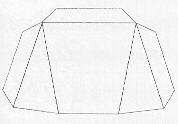
Pattern for Air Vent Outlet (to scale, but probably not full size)
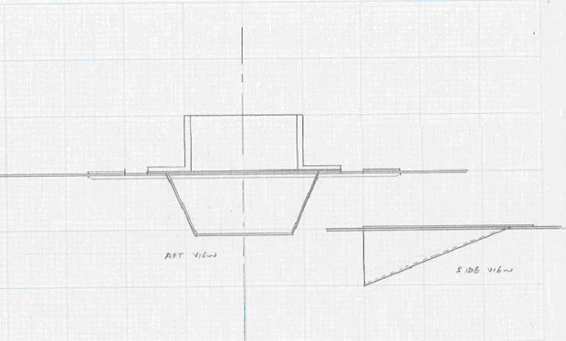
Hand sketch of air vent outlet assembly. The aft facing opening of the air vent outlet 'scoop' was sized to provide the same cross sectional opening area as the cross section of the 2-1/2 inch SCAT duct to which it connects. (Not to scale)
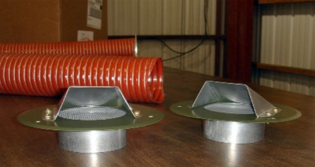
Outlet air vents assembled onto inspection plate covers and flanges. Flanges are machined aluminum parts from Aircraft Spruce.
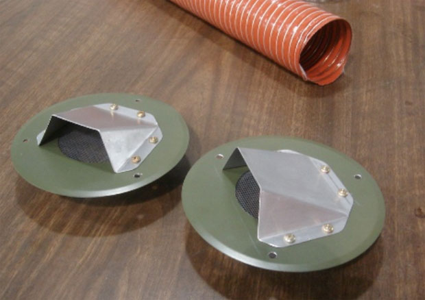
Another View of the Outlet Air Vents. Vent 'scoops' are fabricated from 0.020 2024-T3 aluminum using hand tools and a sheet metal brake. These inspection plate covers were installed earlier and are from a Univair kit for center-section AD compliance.
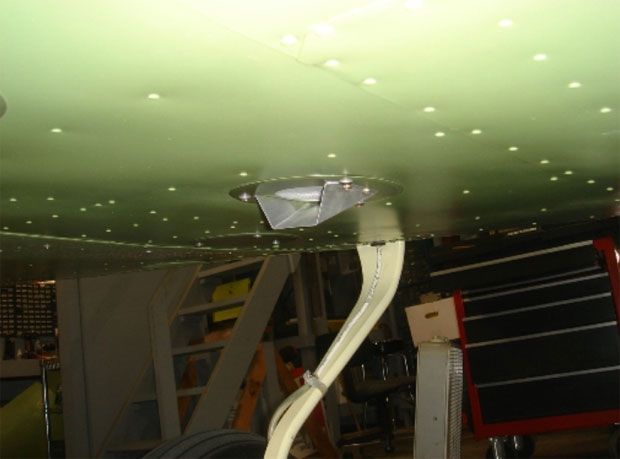
Outlet Air Vent located under wing stub. This is the left side wing stub. Same installation on right hand wing stub.
2-1/2 inch SCAT duct is connected to these flanges with hose clamps, and the duct then is routed through the wing stub under the wingwalk area and into the fuselage aft of the main spar carry-through. These ducts pass through existing lightening holes in the same manner as the previously mentioned factory installed right wing air intake SCAT duct. No holes of any type are drilled in the wing or fuselage structure for this installation. The SCAT ducts enter the fuselage just aft of the main spar carry-through. This area is located under the two seats.
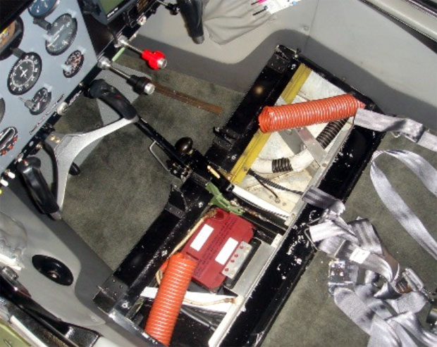
Air duct enters through existing lightening holes in wing stub ribs. When the sheet metal cover and the flanges are installed, the duct is held in place outboard of the angled wing rib parts that are visible in this photo. The SCAT duct does not come near the ship battery, and is physically separated from the battery by the angled rib when the cover is installed.
A factory-original 0.020 inch thick non-structural aluminum sheet covers this area. One 2-1/2 inch hole is cut in each end of this non-structural cover, and an aluminum flange and a piece of vinyl screen are attached to the underside of the 0.020 cover with four each No. 6 AN screws and nuts. The SCAT duct is attached to these flanges with hose clamps. The holes, screens and flanges are underneath the pilot and passenger seat and are out of view and physically protected by the seat assemblies. The areas below the 0.020 cover that mounts the flanges have ample clearance to accommodate the SCAT duct and the ducts are not located near any moving parts or controls
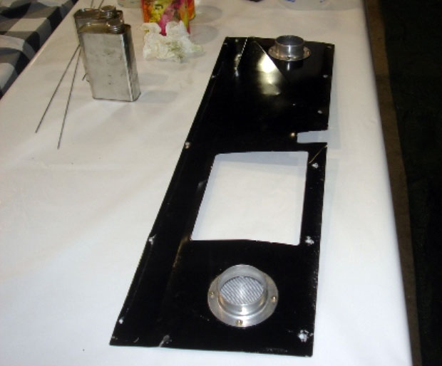
Bottom view of the piece of metal that covers the under-seat area. Large cutout is battery access opening.
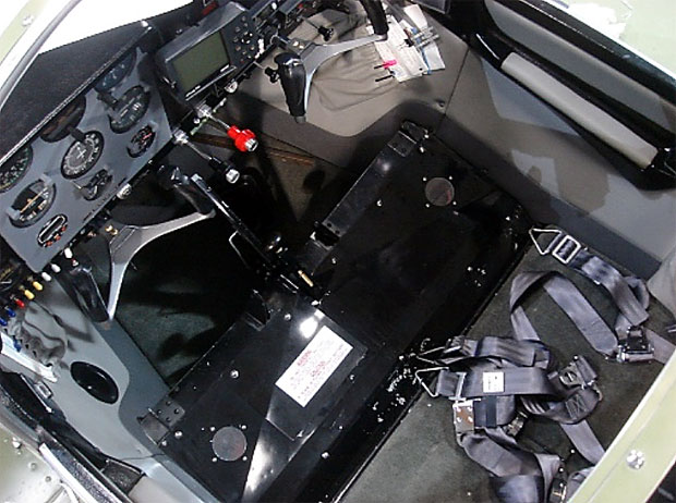
View showing flanges and screens mounted on non-structural 0.020 sheet metal cover under seats. Screens prevent objects from falling into SCAT duct. When the seats are installed, the openings are completely hidden under the seats and are not visible.
No modifications to any structural parts were made for this installation, and the entire kit can be removed and the airplane returned to its previous state by removing the kit, installing the two original (undrilled) inspection plate covers, and replacing the cockpit under-seat aluminum cover with a new 0.20 aluminum piece. No holes were drilled in the airframe for this installation.
Approval:
After consulting with the local FSDO, the installation of this vent kit was signed off in the airframe logbook by my A&P/IA as a minor modification in accordance with 14 CFR Part 43, Appendix A. A new Weight & Balance sheet was also provided by the A&P/IA. Note that other FSDO's or other A&P's may or may not consider this to be a minor modification, so local approval should be obtained prior to installation of this kit.
Results:
Flight testing of this system showed that ventilating airflow in the cockpit is increased substantially, although I have no means of measuring the increase quantitatively. In flight, there is a noticeable amount of suction when one places a hand or a sheet of paper over the screens and flanges in the cockpit, so air is definitely being exhausted through the system.
Cruise airspeed tests conducted at 8500 feet at normal cruise power settings before and after the installation revealed no discernable change in cruise airspeed. These tests included comparison of both indicated airspeed and calculated airspeed using the GPS groundspeed readout with testing at 8 compass headings both before and after the kit was installed. Stall tests were conducted both before and after the kit was installed with no discernable difference in either power-on or power-off stall speeds (38 mph IAS power-on, 48 mph IAS power-off).
If desired, during winter operation the vent system can be disabled simply by blocking off the screened flanges under the seats with tape, or by installing aluminum covers over the flanges. I did not find it necessary to do so during cold weather operations here in South Carolina since the increased outflow also results in increased cabin heat flow when the cabin heat is turned on.
Disclaimer:
The author accepts no responsibility whatsoever for the accuracy, effectiveness, use or misuse of this information. Use at your own risk.
''Wayne DelRossi
Alon N55618F
April 11, 2011''