Alon Control Column Disassembly and Inspection
1. Now that the control column is out of the airplane, I suggest taking several digital photos of it before disassembly. Take close-ups of every part of it so that you will have a reference to use when you reassemble it later. The Alon parts manual does not have a drawing of this assembly, so the manual is of almost no use for reassembly. It may also be useful to measure and record the distance between the pins that attach the chains to the cables as a reference for reassembly. On my airplane this measurement was 13-7/16 inches. Knowing this measurement will help get things back in close to the same place when reassembling the column. This measurement does not need to be very exact though, since the rigging of the chains and cables will be adjusted once the column is reinstalled in the airplane. The measurement just gets you in the ballpark initially. Also, take note of which way the taper pin holes in the u-joints are facing when the center control shaft is centered. This will help when reinstalling the sprocket shafts and the cable and chain assembly. You don't want to reassemble the whole thing and get it back in the airplane just to discover that the taper pin holes in the u-joints are facing the wrong direction. Again, digital photos are a big help.
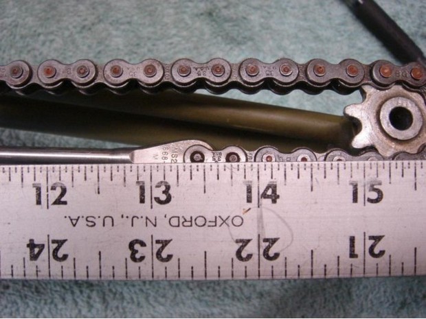
2. Note for future reference how much tension the chain is under by deflecting it up and down by hand. Cut the safety wire off of the turnbuckle and loosen (or disassemble) the turnbuckle.
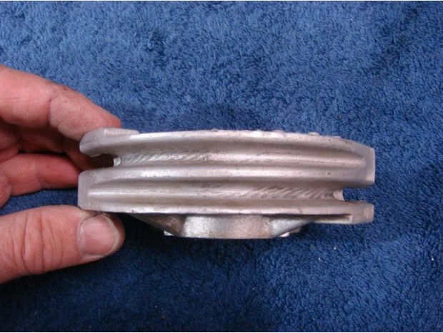
3. Loosen the jam nuts on the cable ends and unscrew the cable end ferrules completely out of the aluminum casting. Inspect the cables for wear and broken strands. Inspect the chain for wear, especially where the links ride on the sprockets. Inspect the grooves in the casting where the cables ride for excessive wear. There will probably be some marks in the casting from the cables, but the casting should not have been cut into by the cables. Any defective parts should be repaired or replaced.
4. Note and record where the large washers on the sprockets are located. My control column had two washers on the sprocket shafts and both washers were on the aft end of the sprocket shaft (closest to the u-joint). These washers are what prevent the shafts from moving fore and aft. Note how the chain sprocket shafts feel in the bushings. Check for excessive clearance. There should be virtually no detectable movement when pushing the shafts from side to side or up and down in the bores of the bushings. There should also be virtually no fore and aft movement when trying to push the shafts in and out of the bushings.
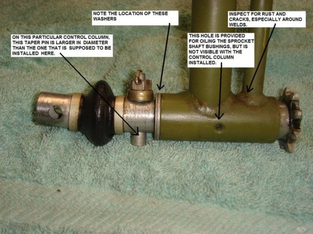
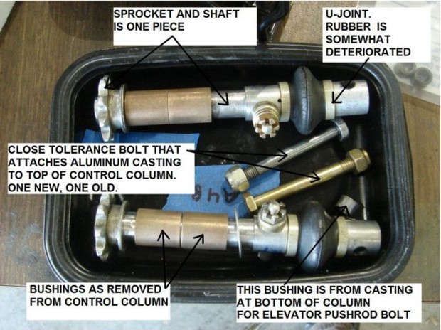
5. Permanently mark the sprocket shafts 'Left' and 'Right' so they can be put back in the same positions. Remove the remaining taper pins from the u-joints and sprocket shafts. Remove the u-joints and remove the sprockets and shafts. Inspect the sprockets and shafts for wear. The shafts can be checked for wear and 'out of round' using a micrometer. You will probably find that the shafts are slightly worn and out of round. In addition, the part of the shaft that was in contact with the bushings will be worn, while the part of the shaft that rides between the two bushings (the middle section of the shaft) will have little or no wear. These shafts will be cleaned up later.
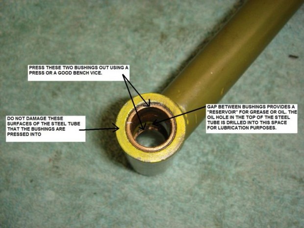
6. If there is any detectable slop or wear between the shafts and the bushings, then the bushings should be replaced. If the sprocket shaft bushings are to be replaced (highly recommended), then press the old bushings out of the steel tubes at outboard ends of the control column. This is best done using a hydraulic press, but a good vice should be strong enough to press them out. Use care to prevent damage to the steel tubes that the bushings are pressed into. Installation and reaming of the new bushings is described below.
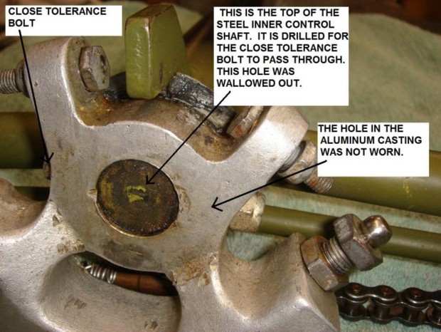
7. Hold the bottom of the center control shaft between two blocks of wood (or other padding) in a vice. Loosen the nut on the close tolerance bolt that fastens the top aluminum casting to the top of the center control shaft. Grab the aluminum casting and try to wiggle it on the center shaft. There should be no play at all between the aluminum casting and the center control shaft. If there is play here, then this is a source of slop between the ailerons and the control wheels. On my control column, I found that the close tolerance bolt was not noticeably worn, and the holes in the aluminum casting were not worn, however the bolt hole through the top of the steel center control shaft was wallowed out. This can be checked by removing the aluminum casting and putting a new close tolerance bolt in the hole in the center control shaft and checking for slop between the bolt and the hole. If there is any slop between the hole in the steel shaft and the new close tolerance bolt, then this clearance needs to be fixed. One method of doing this is to install a taper pin in place of the close tolerance bolt. In my opinion, a taper pin is what the factory should have installed here in the first place. A method of installing a taper pin in this location is described below.
8. With the top aluminum casting removed, check for play between the center control shaft and the bearings that it rides in. This can be accomplished by holding the outer tube of the control column in a vice and trying to wiggle the top and the bottom of the inner shaft from side to side in the outer tube. There should be no side to side movement at all. The original Alon bearings for this shaft were made from a plastic or nylon material. If these bearings have never been replaced, then they are probably well worn. Wear here allows the center control shaft to move from side to side in the control column, which can result in additional aileron play. The reason that this causes play between the control wheel and the ailerons is that when the control wheel is moved, the first bit of motion causes the inner control shaft to rock from one side of the top bearing to the other, before the inner shaft starts to turn. Eliminating this play results in the inner shaft turning as soon as the control wheel is moved. Replacement of these bearings is described below.
9. Remove the center control shaft from the control column and remove the nylon bearings. Note that the nylon bearings are not both the same. Check to see if there is any shim stock between the outside diameter of the nylon bearings and the inside diameter of the outer control column tube. If there is shim stock here, retain it for future use. These nylon bearing pieces will not form a tight fit with the center control shaft without being backed by shim stock. Inspect the inside of the control column tube as well as the center control shaft.
10. The two sealed bearings in the aluminum casting at the bottom of the control column can be removed next. These bearings are pressed into the aluminum casting and can be pressed out using a vice and a couple of appropriately sized sockets. On my airplane, there were small indents around the bore of the hole in the aluminum where the bearing had been slightly swaged in place after being installed, evidently in an attempt to prevent the bearing from coming out. This swaging did not prevent the bearing from being removed, and in my opinion, it really serves no purpose since the bearing is very tight in the bore of the hole in the aluminum. Even if the bearing did work out of the aluminum, the channels in the airframe that the bearings are bolted to would prevent them from coming completely out anyhow.
11. Press out the small bushing in the bottom aluminum casting that the elevator pushrod bolt goes through.
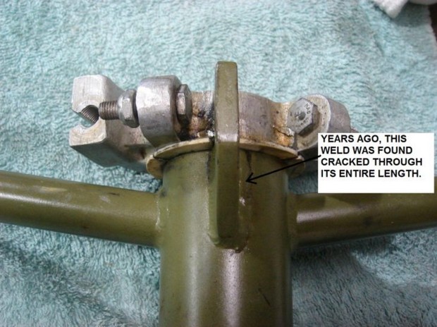
12. The control column should be fully disassembled now. Carefully inspect the control column and all of the various parts that were removed. Look closely at all of the welds on the control column assembly. Years ago on my airplane we found that the steel tab that the aileron stop bolts hit had a cracked weld. This was evidently cracked due to the ailerons banging back and forth in the wind when the airplane was parked. Also check that the bottom aluminum casting is firmly attached to the control column outer shaft. This part is riveted in place with several large rivets.
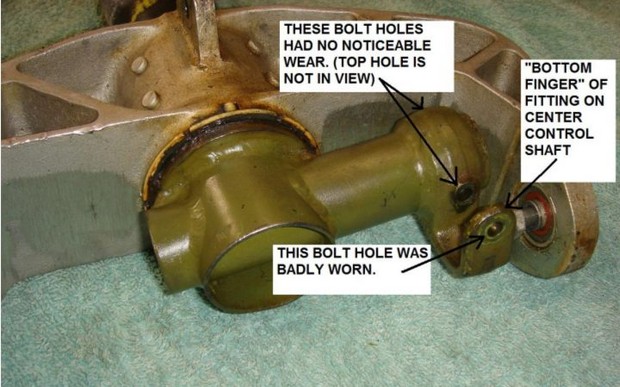
13. Inspect the holes in the fitting at the bottom of the center control shaft that the bolt for the aileron pushrod goes through. This hole is drilled through the cylindrical part of the fitting and through the 'bottom finger' of the fitting. On my control column, the hole through the 'bottom finger' of the fitting was wallowed out to the point that it was egg shaped. The other two holes appeared to be in good condition, although they were a sloppy fit on the bolt that came out of them. The original bolt called out in the parts manual is not a close tolerance bolt. Repair to this bolt hole is described below.
14. If desired, the control column can be media blasted to remove all rust and paint from it. Before doing this, all bearing surfaces or machined surfaces should be protected with masking tape. In particular, the parts of the outside diameter of the inner control shaft that ride on the nylon bearings should be protected from the blast media. You don't want these surfaces to be roughened up by the blast media. Also tape up any holes that bearings or bushings press into. After media blasting the parts, inspect them again for cracks and defects.
| << previous Removal | next Repair and Reassembly >> |