Alon Control Column Repair and Reassembly
1. Repair parts for the control column are generally available from Skyport and Univair. When I reassembled the control column and reinstalled it in the airplane, I used close tolerance bolts instead of the standard bolts called out in the parts manual. Standard bolts are typically several thousandths of an inch smaller than their stated diameter. Close tolerance bolts are typically only about 1 or 2 thousandths of an inch smaller than their stated diameter. Because all of these bolts go through machined holes, through bearings or through rod ends, there is no reason to have any extra clearance between these bolts and the holes that they go through. In fact, the extra clearance here just allows the bolt to move around in the hole and causes the bolt and hole to wear faster than it should. Like they say, 'Slop gets more slop.' And we're trying to get rid of all the slop that we can. So in general, I replaced AN3 bolts with AN173 bolts, and replaced AN4 bolts with AN174 bolts. The long AN23-36 bolt that connects the aileron pushrod to the 'bottom finger' of the center control shaft was replaced with an AN173-23A close tolerance bolt which was then drilled in the proper location for a cotter pin.
2. Start the reassembly of the control column by pressing in the four new sprocket shaft bushings. These bushings are Univair P/N F521186. The bushings can be coated with grease or oil and then pressed into the steel tubes at the outboard ends of the control column with either a press or a vice. I used a vice and padded the jaws with a couple of pieces of aluminum. The bushings should be pressed in so that they are flush with the ends of the steel tubes that they are pressed into. Check the fit of the sprocket shafts in these bushings after installing the bushings. You will probably find that the shafts will not go into the bushings at all. The bushings have to be reamed to fit the sprocket shafts. Before reaming the bushings though, the shafts need to be cleaned up so that they are as round and even as possible. I reconditioned the shafts by clamping the sprocket end of the shafts between two blocks of soft wood in the vice and then used a micrometer and very fine cloth sandpaper (crocus cloth) to dress up the shafts. The idea is to take off the minimum amount of metal possible while eliminating high spots and rough edges on the shafts. The best way (in my opinion) to ream these bushings is with an adjustable reamer. If you use a standard, non-adjustable reamer on these bushings, you will probably take out too much metal, and will end up with slop in your brand new bushings. An adjustable reamer allows you to start out well under ½ inch and gradually work your way up to where the shafts just fit in the bushings. The adjustable reamer has a mechanism on it that allows you to adjust the blades outward by very small amounts. I borrowed a ½ inch adjustable reamer from a machinist friend of mine, and he warned me to make very, very tiny adjustments to the reamer and to check the fit of the shafts very often. He warned me that one minute the hole would be too small, and the next minute it would be too big. Heeding his advice, I took my time and made very small adjustments to the reamer and was able to get the shafts so that they turned freely, but had no slop whatsoever. While checking the fit, I also did a little further work on the shafts where I could tell that they had a high spot that was dragging in the bushings. It took about 2 hours per side to get a perfect fit. Once the bushings are reamed, set the shafts aside for assembly later.
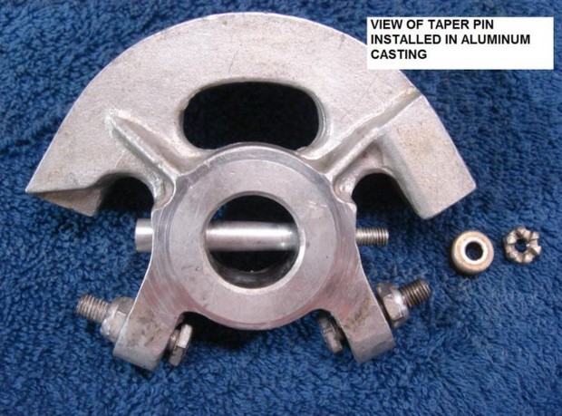
3. The u-joints on my control column had been replaced recently, so I did not have to replace them while rebuilding the control column. I will share one piece of advice however concerning the taper pins and the holes that they go into. When installing new u-joints, the taper pin holes in the new u-joints have to be drilled and then reamed. It is very easy when reaming these holes to make the holes too big. The taper pins have to sit in the holes at the right depth so that enough of the head of the taper pin is exposed and also so that the nut and special washer lines up properly for the cotter pin to be installed. When fitting the taper pin, remember that the nut will pull the pin down into the hole further than you can push it into the hole by hand. Be careful not to ream the hole too much. It is better to go very slowly and get it right than to ream it too far and have a real mess on your hands. If the hole is reamed too far, there are oversized taper pins of the proper length that can be used, but they can be difficult to find, and they require the use of a different size tapered reamer.
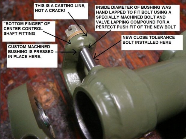
4. The worn out hole in the 'bottom finger' of the center control shaft was difficult and expensive to repair. This hole cannot be drilled out to the next larger size for use with an oversized bolt because the bolt has to go through the small rod end on the aileron pushrod. In addition, I didn't want to remove that much metal from the bore of the three holes due to strength reasons. In order to fix the problem, I had a machinist fabricate a small steel bushing and bore the hole in the bottom finger to a larger diameter to accept the bushing. The machinist jigged up the inner control shaft in a milling machine and used the upper two bolt holes, which were not worn, to center the worn hole on the milling machine. He then line-bored the worn hole to a larger diameter so that the bushing would be a press fit into the bored hole and would be perfectly in line with the other two holes. The outside diameter of the bushing was milled with a very slight taper so that the bushing can only be inserted from the top side of the bored hole. This was to make it impossible for the bushing to move downward or come out the bottom side of the hole. The hole in the bushing was drilled slightly smaller than the diameter of the AN173-23A bolt that we planned to put through the hole. A spare AN173-23A bolt was turned down in a lathe so that it could be used as a tool to hand lap the hole in the bushing using valve lapping compound. The end result was that the new close tolerance bolt pushes into position with considerable pressure applied by hand. The fit of the bolt in the hole is perfect, with no play whatsoever. If this hole is worn in your inner control shaft fitting, I suggest seeing if a new part is available from Univair or Skyport. If not, then the installation of a bushing is the only other fix that I can think of. We did consider welding this hole up and redrilling it, but we did not know what kind of metal it was made of, and we were concerned about changing the heat treat of the metal.
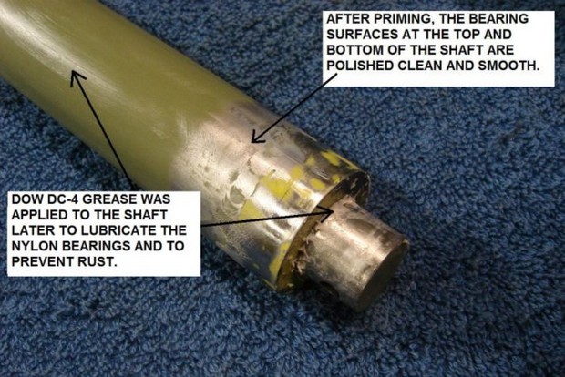
5. The next step in the reassembly process is to paint the control column and inner control shaft with epoxy primer. The surfaces that are to have bearings installed, and the areas of the inner shaft that are to ride in the nylon bearings should be masked off so that they are not painted. Also don't forget to mask off the new sprocket shaft bushings. When spraying the inner control shaft remember that the shaft must be inserted up through the new nylon bearings, and that those bearings should be riding on bare shiny metal. You don't want the paint or primer on this shaft to be too thick, or it will interfere with sliding the shaft through the bearings. You don't want paint or primer between the metal and the bearings because the paint will just wear off and result in unnecessary slop between the shaft and the bearings. After spraying the inner control shaft, polish up the bearing surfaces with fine sandpaper or crocus cloth.
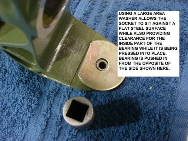
6. The bearings in the bottom aluminum casting can be installed next. These bearings are MS27640-4 sealed bearings. These bearings can be pressed into place with a press or a vice. Be careful not to apply any pressure to the center part of the bearing that the bolt goes through. All pressure should be applied only to the outside race of the bearing. I used a large socket and a large area washer with one side trimmed off on one side of the bearing and a smaller socket that just fit the outside race of the bearing to press the bearings in place. Note that these bearings must be spaced the proper distance apart from each other in order to have them go back into the channels in the airframe. When I went to install the control column, I found that it would not fit back between the channels easily because the bearings were not spaced correctly. I had to remove the control column and adjust the bearings slightly in the casting in order to get the column to drop back into the channels.
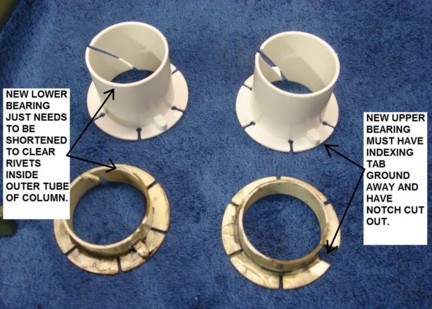
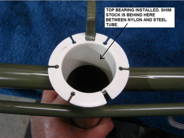
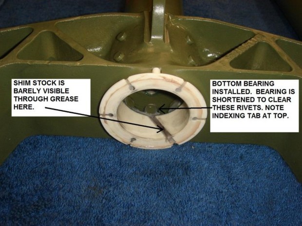
7. The nylon inner control shaft bearings can be fitted next. There has been some discussion about replacing these bearings with bearings made from other materials such as bronze, but in my opinion, the nylon ones work fine in this application if they are properly installed. The Alon parts manual specifies two different Thompson nylon bearings (or bushings) for these bearings. The upper bearing is specified as a Thompson 2353A, Type 6, and the lower bearing is specified as a Thompson 2353A, Type 5. I was unable to locate parts with these part numbers anywhere. Skyport stocks these nylon bearings as P/N 24L24F. These parts appear to be very similar to the ones that were installed in my airplane originally. The parts do require some slight modification in order to fit properly. The upper bearing needs a notch cut out of the flanged area in order to clear the steel aileron stop tab that is welded to the outer control column tube. It also needs to have the small indexing tab ground off, as it is not needed for the upper location. The cylindrical part of this bearing that extends down into the outer control column tube is longer than the one that came out of the airplane, but I saw no reason to shorten the new one to match the old one. The new one now has more bearing surface area and should last even longer than the original. The lower bearing just has to be shortened so that it does not extend in to the rivets that hold the bottom aluminum casting on. The indexing tab must be retained on the lower bearing since the control column has a cut-out to receive it. These bearings can be easily modified using hand tools or a Dremel tool. The size of the notch and the length of the bottom bearing can be test-fit on the control column and adjusted accordingly.
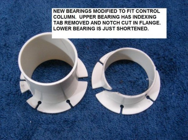
8. These bearings when installed in the control column will result in a very sloppy fit with the inner control shaft. In order to take up this clearance, thin brass shim stock should be used to wrap around the part of the bearing that fits down into the tube. Adding shim stock will result in a tighter fit. It is a matter of trial and error to determine how much shim stock makes the fit just right. I found that I had to install both bearings in the control column with some shim stock around each one, and then test fit the inner control shaft in the bearings. Coat the shaft and bearings with a suitable grease to lubricate the shaft and bearings before assembling them. I used Dow DC-4 grease and it seems to be working fine. You can test just the upper or just the lower bearing by removing the other one, but the final fit should be made with both bearings installed. You may have to pull the lower bearing out of the outer control column tube in order to insert the inner control shaft, since the primer on the inner shaft may not slide past a properly adjusted lower bearing. In this case, just insert the lower bearing by letting the bottom of the inner control shaft push it into place. I installed just enough shim stock to cause the shaft to bind slightly on the nylon bearings and then I spun the inner shaft in the bearings to wear the bearings into the shaft. I used a wooden block with a stud sticking out of one end that fit into a 3/8 inch drill chuck, and the other end of the wooden block was shaped to fit up into the bottom end of the inner control shaft. Doing this caused the bearings to wear in a bit and resulted in a nice fit between the bearings and the inner shaft. Keep in mind while doing this that just like the slop in the system is additive, the tightness or binding in the system is additive as well. If everything you put together is a little bit tight or hard to turn, then when it is all completely put together, you may not be able to move it at all. You don't want anything tight or binding when doing this, you want it free to turn and free to move, but without any excess play.
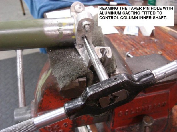
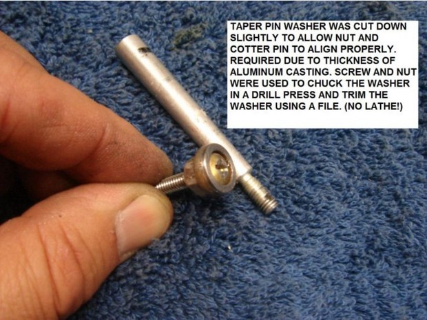
9. The next step in reassembly is to fit the top casting onto the center control shaft. If the bolt hole in the aluminum casting and in the center control shaft is not worn, then this can be assembled using a new close tolerance bolt. On my control column the hole in the steel piece was worn out. I considered drilling this assembly to take a larger bolt, but the clearance for removing and installing the existing bolt and nut were pretty tight, and I did not think that at 5/16ths inch bolt head would clear the casting. As I mentioned earlier, this fastener should have been a taper pin to begin with. An AN386-2-15 taper pin is the correct size for this application. I bought two of these pins from Tex-Air Parts, Inc. in Addison, Texas. I also bought the proper taper pin reamer from a local tool distributor. The existing ½ inch holes in the steel and in the aluminum were reamed as an assembly with the tapered reamer. Because of the thickness of the aluminum, and the need to properly center the taper pin in the assembly, I had to trim down one of the special cupped taper pin washers so that it was shorter than it was originally. This allowed the nut and cotter pin to properly align with the cotter pin hole in the taper pin. With the taper pin installed there is no play whatsoever between the aluminum casting and the inner control shaft.
10. The small bushing for the elevator pushrod bolt can be installed in the bottom aluminum casting next. The Univair P/N for this steel bushing is S301-4. This bushing can be pressed in place using a vice or a press.
11. If desired, any finish painting can be done at this time. I sprayed the outer control column tube with Krylon Tool Box Paint, which is very durable and has a nice hammered metal look to it. When that paint is thoroughly dry, the control column assembly can be completely reassembled.
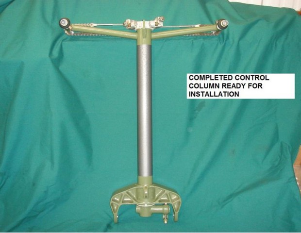
12. Be sure that all components are well lubricated when reassembling them. The sprocket shafts can be coated with light grease or as advised in the Alon service manual. Be sure to install the right one on the right side and the left one on the left side. Reinstall the sprocket shaft washers, u-joints and the taper pins that connect them to the sprocket shafts. Do not over tighten the taper pin nuts. It does not take much tightening to lock the taper pins into the tapered holes. Put enough grease on the nylon inner control shaft bearings to last forever, as hopefully you will never be taking this apart again. The chain and cable assembly can be reinstalled, paying attention to the orientation of the u-joints. Try to get the turnbuckle and cable end adjustments adjusted to about where they were before, but all of this will need to be readjusted later. Do not safety wire the turnbuckle because it will need to be adjusted after the control column is reinstalled and the controls are reconnected.
| << previous Disassembly and Inspection | next Installation >> |